MAGNET
From KIP Wiki
⧼kip-jumptonavigation⧽⧼kip-jumptosearch⧽
Operation and Control


- Power Supply : OXFORD IPS 120-10 (Max.12 Amp @10Volt)
- Software Remote-control: IPS_120-10_v05.vi
- ! Change of Range when increasing the current at ~4.3A, when decreasing at ~3.4A! Don't get scared by the noise :)
- Persistent current switch:
- Upper magnet - BOX VII, X9:1/4 ,RHeater(4K)=135.
- IHeater=55mA. A TVL-10 is used as precision current supply.
- The region of the experimental platform between the first nuclear stage and the dilution refrigerator is compensated to 5mT when both magnets are at their full field.
- Resistance of power cable between current supply and magnet: R=0.6 Ohm

Magnetisation and Demagnetisation Procedure

- After ramping the magnet the first nuclear stage must be precooled again. The temperature dependence varies as T~t-1/3.
- The first nuclear stage was demagnetized by reducing the field in steps by a factor of 2 to a final field of few mT.
- Sweep Rate B>0.5T : R=2T/h.
- Sweep Rate B<0.5T : decrease by a factor of 2 proportional to the field.
Upper Magnet (UM)

- Connection on window side of cryo. Power-cable are marked red (+) and blue (-).
- Bmax = 8T, diameter 100mm.
- I/B-Conversion: B(I) = 0.099 T/A * I[A] , ( 80.68 A = 8 T )
- Sweep Rate: 1 T/h = 10 A/h = 0.167 A/min
- Heater of PCS: BOX VII, X9:(1/4)
Lower Magnet (LM)

- Connection on door side of cryo. Power-cable are marked green (-) and white (+).
- Bmax = 9T, diameter 50mm.
- I/B-Conversion: B(I) = 0.115 T/A * I[A] , ( 78.4 A = 9 T )
- Sweep Rate: 1 T/h = 8.7 A/h = 0.145 A/min
- Heater of PCS: BOX VII, X10:(1/4)
Connection
- To Power supply: M6 (#13 box wrench, #6 Allen key).
- To Upper Magnet: Connection on window side. Power-cable are marked red (+) and blue (-).
- To lower magnet: Connection on door side of the cryostat. Power-cable are marked green (+) and white (-)
- AMP-Plug (connected witch BOX VII): Control of two persistent current switches, read-out of two Pt-100 and of two heaters.
- The persistent current switches are used to create and maintain the magnetic fields with the current source.
- With the help of the two attached Pt-100 Thermometers at the bottom (BOX VII, X6) and top (BOX VII, X7) of the magnet you can monitor the temperature during the precooling precess with liquid nitrogen (LN).
- Finally you can also use the two heaters consisting of two solder sticks to decrease the waiting time while warming up the cryostat.
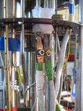
Connection to upper magnet.
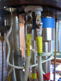
Connection to lower magnet.
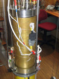
Black AMP-Plug.
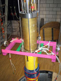
Installing the magnet with three supporting rods.
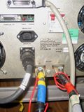
Connection of the current wiring at the rear panel of the power supply.


AMP PLUG

The magnet is controlled via BOX VII. Therefor BOX VII is connected by a Amphenol 32PIN Plug with the AMP 24PIN male jack of the magnet. In doing so not all pins of the magnet are connected with the Amphenol Plug at the top of the cryostat! These pins are number: 17-23.
| AMP | Amph. | BOX VII | FUNCTION |
|---|---|---|---|
| 1 | K | X8:4 | Heater magnet |
| 2 | F | n.c. | --- |
| 3 | b | X7:4 | Pt-100, top (-) |
| 4 | Y | X7:1 | Pt-100, top (+) |
| 5 | a | X6:2 | Pt-100, bottom (+) |
| 6 | J | X8:1 | Heater magnet |
| 7 | M | X6:3 | Pt-100, bottom (-) |
| 8 | G | X6:1 | Pt-100, bottom (+) |
| 9 | Z | n.c. | --- |
| 10 | W | n.c. | --- |
| 11 | c | X9:4 | PCS Heater UM |
| 12 | N | X9:1 | PCS Heater UM |
| 13 | X | X10:1 | PCS Heater LM |
| 14 | h | X10:4 | PCS Heater LM |
| 15 | j | X7:2 | Pt-100, top (+) |
| 16 | g | X7:3 | Pt-100, top (-) |
| 24 | H | X6:4 | Pt-100, bottom (-) |