PINBAR: Difference between revisions
From KIP Wiki
Ō¦╝kip-jumptonavigationŌ¦ĮŌ¦╝kip-jumptosearchŌ¦Į
| Line 465: | Line 465: | ||
|- |
|- |
||
! 7 |
! 7 |
||
| PHS @4K || X(16) || - || sc with 2,7,8,11,12,13,14,17,18,20 at AMP Test-BOX |
| PHS @4K || X(16) || - || sc with 2,7,8,11, 12, 13,14,17,18,20 at AMP Test-BOX |
||
|- |
|- |
||
! 5 |
! 5 |
||
| Line 499: | Line 499: | ||
|- |
|- |
||
! 6 |
! 6 |
||
| F1 at MC |
| F1 at MC || b(10) || II, - || R<sub>S0:6-F1</sub>=14{{O}} |
||
|- |
|- |
||
! 4 |
! 4 |
||
| F3 at MC |
| F3 at MC || - || - || R<sub>S0:4-F3</sub>=14{{O}} |
||
|- |
|- |
||
! 2 |
! 2 |
||
| no |
| no connection on backside || - || - || - - |
||
|} |
|} |
||
</div> |
</div> |
||
Revision as of 11:52, 18 October 2010
PIN BAR
- All values are including the measuring cables!
- Nomenclature:
- Greek numbers = Filter Box on the top
- Xi = Plug at the corresponding Filter Box (e.g. : VI, X3 = Plug X3 at Filter Box VI ).
- Xi:j = Pin j at Plug Xi (e.g. : VI, X3:4 = Pin 4 at Plug X3 at Filter Box VI ).
- R1/2 = Resistance between Pin 1 and 2 directly measured at a corresponding PIN BAR.
- RX3:1-2 = Resistance between Pin 1 at Plug X3 of the Filter Box and Pin 2 at the PIN BAR.
- RX3:1/2 = Resistance between Pin 1 and Pin 2 at Plug X3 of the Filter Box.
MIXING CHAMBER
There are six PIN BARS (A-F) mounted on the mixing chamber. Each consists of 16 PINS arranged in two columns.
BAR A

| PIN | CONNECTION | BOX | COMMENT |
|---|---|---|---|
| 15 | nc | ? | |
| 13 | nc | ? | |
| 11 | nc | ? | |
| 9 | nc | ? | |
| 7 | nc | ? | |
| 5 | nc | ? | |
| 3 | nc | ? | |
| 1 | nc | ? |
| PIN | CONNECTION | BOX | COMMENT |
|---|---|---|---|
| 16 | nc | ? | |
| 14 | nc | ? | |
| 12 | nc | ? | |
| 10 | nc | ? | |
| 8 | nc | ? | |
| 6 | nc | ? | |
| 4 | nc | ? | |
| 2 | nc | ? |
BAR B

| PIN | CONNECTION | BOX | COMMENT |
|---|---|---|---|
| 15 | nc | ? | |
| 13 | nc | ? | |
| 11 | nc | ? | |
| 9 | nc | ? | |
| 7 | nc | ? | |
| 5 | nc | ? | |
| 3 | nc | ? | |
| 1 | nc | ? |
| PIN | CONNECTION | BOX | COMMENT |
|---|---|---|---|
| 16 | nc | ? | |
| 14 | nc | ? | |
| 12 | nc | ? | |
| 10 | nc | ? | |
| 8 | nc | ? | |
| 6 | nc | ? | |
| 4 | nc | ? | |
| 2 | nc | ? |
BAR C
- No connection to BOX I, X7-X11!
- NO GROUND!

| PIN | CONNECTION | BOX | COMMENT |
|---|---|---|---|
| 15 | nc | ? | |
| 13 | nc | ? | |
| 11 | nc | ? | |
| 9 | T.P. 9-10 | ? | leads through capillary |
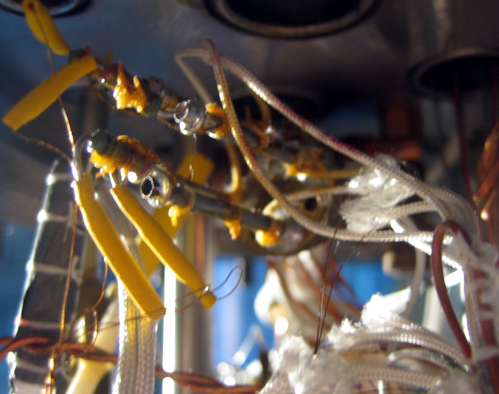
| 7 | CT MC | ? | yellow s.t. |
| 5 | CT MC | ? | 5-8 leads trough textile tube |
| 3 | nc | ? | |
| 1 | nc | ? |
| PIN | CONNECTION | BOX | COMMENT |
|---|---|---|---|
| 16 | nc | ? | |
| 14 | nc | ? | |
| 12 | nc | ? | |
| 10 | T.P. 9-10 | ? | capillary leads to 1K-pot |
| 8 | CT MC | ? | yellow s.t. + black marked |
| 6 | CT MC | ? | black marked |
| 4 | nc | ? | |
| 2 | nc | ? |
BAR D

| PIN | CONNECTION | BOX | COMMENT |
|---|---|---|---|
| 15 | nc | ? | |
| 13 | nc | ? | |
| 11 | nc | ? | |
| 9 | nc | ? | |
| 7 | nc | ? | |
| 5 | nc | ? | |
| 3 | nc | ? | |
| 1 | nc | ? |
| PIN | CONNECTION | BOX | COMMENT |
|---|---|---|---|
| 16 | nc | ? | |
| 14 | nc | ? | |
| 12 | nc | ? | |
| 10 | nc | ? | |
| 8 | nc | ? | |
| 6 | nc | ? | |
| 4 | nc | ? | |
| 2 | nc | ? |
BAR E

- Assignment of pins at Bar E. The number of each pin corresponds with that of the AMP-BOX.
- Resistance between Box VI and Pins: RVI-E ~ 280
- All values are including measuring cables!
- NO GROUNDS!

| PIN | CONNECTION | BOX | COMMENT |
|---|---|---|---|
| 1 | ET ST | VI, X1:1 | |
| 2 | ET ST | VI, X1:2 | |
| 3 | FPD | VI, X2:1 | |
| 4 | FPD | VI, X2:3 | |
| 5 | FPD Degauss | VI, X3:1 | R5/23=155.4 |
| 6 | nc | VI, X3:2 | |
| 7 | nc | VI, X4:1 | |
| 8 | HZ(?) | VI, X4:2 | R8/26=1k , T.P. leads to strange heat sink at 1K |
| PIN | CONNECTION | BOX | COMMENT |
|---|---|---|---|
| 19 | ET ST | VI, X1:3 | |
| 20 | ET ST | VI, X1:4 | |
| 21 | FPD | VI, X2:4 | |
| 22 | FPD | VI, X2:3 | |
| 23 | FPD Degauss | VI, X3:4 | RX3:1-4=714 |
| 24 | nc | VI, X3:3 | |
| 25 | nc | VI, X4:4 | |
| 26 | HZ(?) | VI, X4:3 | RX3:1-4=1.65k |
BAR F

- Resistance between Pin 6,7 and 8 is measured with connected Filterbox.
- Number in brackets "()" is the corresponding AMP-TEST-BOX connection.
- F1-F4 are connected to PIN-BAR S0 at Still-Level and via there to BOX-II.
- NO GROUNDS!
| P | CONNECTION | PLG | BOX | COMMENT |
|---|---|---|---|---|
| 15 | T.P. 15/16, ends at Still! ->n.c.! | S | I, X10:2 | RX10:2-15=172.7 |
| 13 | nc | J | I, X9:3 | RX9:3-13=169 |
| 11 | nc | K | I, X9:4 | RX9:3-11=168.6 |
| 9 | nc | L,a | I, X10:3 | RX10:3-9=177.9 |
| 7 | CT (FT) on MC, S5 at LR700 | c | I, X6:4, X6:3 | R7/8=122 |
| 5 | nc | V | I, X11:1 | RX11:1-5=68.9 |
| 3 | nc | - | STILL S0:4 | RS0:4-3=14 |
| 1 | nc | b | II,(10) , S0:6 | RII,b-1=69 |
| P | CONNECTION | PLG | BOX | COMMENT |
|---|---|---|---|---|
| 16 | T.P. 15/16 | M,Z | I, X10:4 | sc with PIN 10 on backside |
| 14 | nc | M,Z | I, X10:4 | sc with PIN 10 on backside |
| 12 | nc | M,Z | I, X10:4 | sc with PIN 10 on backside |
| 10 | nc | M,Z | I, X10:4 | RX10:4-10=47.7 k |
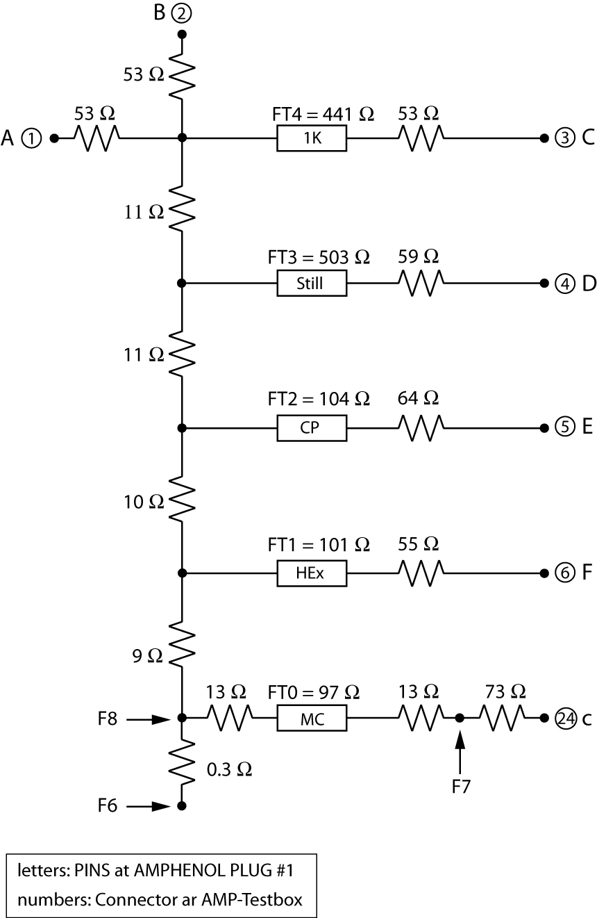
| 8 | CT (FT) on MC, S5 at LR700 | A-F | I, X2-X6:1-4 | see here:circuit diagram |
| 6 | nc, same function as F8 | A-F | - | R6/8=0.3, R6/7=122 |
| 4 | nc | - | S0:1 | RS0:1-4=14 |
| 2 | nc | Y | II,(21) , S0:3 | RII,Y-2=69 |
STILL
There are seven PIN BARS (0,A-F) mounted on the mixing chamber. Each consists of 16 PINS arranged in two columns.
BAR 0

- Connected to BOX II
- NO GROUNDS
- 07-011 are connected to heater of a persistent current switch (PHS) on the bottom of the 4K-flansch (see here)
- The backside of PIN 01,03,04,06 is connected PIN BAR F at the MC.
| P | CONNECTION | PLG | BOX | COMMENT |
|---|---|---|---|---|
| 15 | MC Heater (-) | F(6) | II,X1:2 | |
| 13 | MC Heater (-) | L(23) | - | |
| 11 | PHS @4K | Z(17) | - | RZ-11=50 |
| 9 | PHS @4K | V(11) | - | RV-9=50 |
| 7 | PHS @4K | X(16) | - | sc with 2,7,8,11, 12, 13,14,17,18,20 at AMP Test-BOX |
| 5 | Degauss cable at MC | U | - | nc at MC |
| 3 | F2 at MC | Y(21) | - | RS0:3-F2=14 |
| 1 | F4 at MC | nc | - | RS0:1-F4=14 |
| P | CONNECTION | PLG | BOX | COMMENT |
|---|---|---|---|---|
| 16 | MC Heater (+) | E | II,X1:1 | |
| 14 | MC Heater (+) | D | II, - | |
| 12 | PHS @4K | B | II, - | RB-12=50 |
| 10 | PHS @4K | T | II, - | RT-10=50 |
| 8 | Degauss cable at MC | A | II, - | nc at MC |
| 6 | F1 at MC | b(10) | II, - | RS0:6-F1=14 |
| 4 | F3 at MC | - | - | RS0:4-F3=14 |
| 2 | no connection on backside | - | - | - - |