STILL: Difference between revisions
From KIP Wiki
Ō¦╝kip-jumptonavigationŌ¦ĮŌ¦╝kip-jumptosearchŌ¦Į
┬Ā |
|||
| (20 intermediate revisions by the same user not shown) | |||
| Line 1: | Line 1: | ||
= General Informations = |
|||
=STILL= |
|||
Here are some technical details about the still. |
|||
* Volume: V<sub>Still</sub>=??? . |
* Volume: V<sub>Still</sub>=??? . |
||
* Seven heat sinks are installed on the still. [[PINBAR#STILL|Details klick here]] |
|||
* Still-Shield |
|||
{{clear}} |
{{clear}} |
||
= Still Heater = |
|||
* |
* Connection: BOX II X3:(1-4). |
||
* R<sub>Still</sub>= 1.13 k{{O}}, new heater installed November 2011. |
* R<sub>Still</sub>= 1.13 k{{O}}, new heater installed November 2011. |
||
* I<sub>Still</sub>= 3-5 mA, depending on required cooling power. |
* I<sub>Still</sub>= 3-5 mA, depending on required cooling power. |
||
* The still heater is mounted on the lower side of the still. |
* The still heater is mounted on the lower side of the still and is shielded by a gold plated copper housing. The whole setup is attached to the still by a single screw and is positioned right in the center of the continuous heat exchanger. The wires are shielded by a textile tube and lead from the resistor via a fed-through at the still-flange to the 1K-pot. |
||
<gallery widths="120" heights="160" perrow=" |
<gallery widths="120" heights="160" perrow="4"> |
||
Image: |
Image:Still_heater_00.jpg|New still heater inside copper housing. |
||
Image: |
Image:Still_heater_01.jpg|Still heater mounted on lower side. |
||
Image: |
Image:Still_heater_02.jpg|Wiring along the still and beneath. |
||
Image:Still_heater_03.jpg|Wiring from 1K-pot to Still. |
|||
</gallery> |
</gallery> |
||
| Line 22: | Line 24: | ||
== New Still Heater == |
|||
[[Image:Still_heater_new.jpg|right|thumb|120px|Picture of new still heater.]] |
|||
* Wire: |
|||
** ISOTAN (CuNi44), Isabellenh├╝tte Heusler GmbH KG, Dillenburg. |
|||
** d=50um, r=251{{O}}/m, I<sub>max</sub>=69mA, R<sub>Still</sub>= 1.138 k{{O}} |
|||
* The heater is build up by N=100 turns of a twisted-pair wrapped around the former copper heater-body (h=9.0mm, d=6.5mm). GE-varnish was used to fix the wire and each layer. To protect the heating wires cigarette paper was added between each layer and at the end. Finally the we used dental floss wrapped around the cigarette paper as top layer to fix an shield the wire. |
|||
* A twisted pair of copper wires (d=100mm , R=??{{O}} ) lead from the solder connection at the upper side of the still to resistor beneath it. The copper wires are connected to the heating wire via a solder pad clued on the the top layer of cigarette paper. A textile tube is used to protect the twisted pair. |
|||
{{clear}} |
|||
== Old Still Heater == |
|||
[[Image:Still_heater_old.jpg|right|thumb|120px|Picture of former still heater.]] |
[[Image:Still_heater_old.jpg|right|thumb|120px|Picture of former still heater.]] |
||
| Line 30: | Line 45: | ||
{{clear}} |
{{clear}} |
||
= Still Shield = |
|||
... |
|||
{{ clear}} |
|||
Latest revision as of 08:49, 10 January 2012
General Informations
- Volume: VStill=??? .
- Seven heat sinks are installed on the still. Details klick here
- Still-Shield
Still Heater
- Connection: BOX II X3:(1-4).
- RStill= 1.13 k, new heater installed November 2011.
- IStill= 3-5 mA, depending on required cooling power.
- The still heater is mounted on the lower side of the still and is shielded by a gold plated copper housing. The whole setup is attached to the still by a single screw and is positioned right in the center of the continuous heat exchanger. The wires are shielded by a textile tube and lead from the resistor via a fed-through at the still-flange to the 1K-pot.

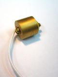
New still heater inside copper housing.
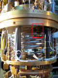
Still heater mounted on lower side.
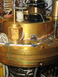
Wiring along the still and beneath.
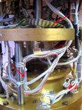
Wiring from 1K-pot to Still.


New Still Heater

- Wire:
- ISOTAN (CuNi44), Isabellenh├╝tte Heusler GmbH KG, Dillenburg.
- d=50um, r=251/m, Imax=69mA, RStill= 1.138 k
- The heater is build up by N=100 turns of a twisted-pair wrapped around the former copper heater-body (h=9.0mm, d=6.5mm). GE-varnish was used to fix the wire and each layer. To protect the heating wires cigarette paper was added between each layer and at the end. Finally the we used dental floss wrapped around the cigarette paper as top layer to fix an shield the wire.
- A twisted pair of copper wires (d=100mm , R=?? ) lead from the solder connection at the upper side of the still to resistor beneath it. The copper wires are connected to the heating wire via a solder pad clued on the the top layer of cigarette paper. A textile tube is used to protect the twisted pair.
Old Still Heater

- Resistance of still heater : RStill=880. Based on the original SHE-manual it was supposed to be ~1k?
! removed November 2011, since it didn't work anymore. One resistance-foil was broken.
Still Shield
...